



 243 322

243
MASONS SUPPLY COMPANY
Oregon (800) 537-3407 ♦ Washington (800) 537-6216
Clackamas | Eugene | West Eugene | Hillsboro | Medford | Portland | Salem | Wilsonville | Ridgefield | Seattle | Tacoma | Woodinville
M A S C O . N E T
TILT-UP/PRECAST
TILT-UP
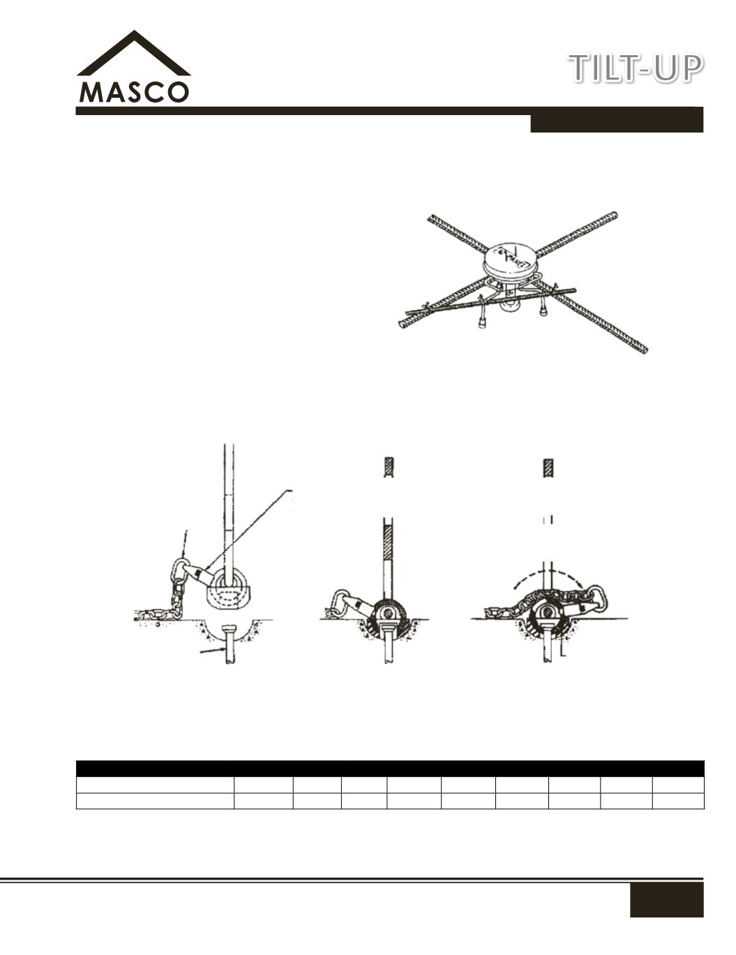
Gyro Tilt Plus System
Insert
- The GTP inserts are simply wired to the rebar
mat at designated points. No special orientation
is required but reasonable care should be taken to
assure that the insert is the correct overall height for
the panel and remains perpendicular to the panel
face during concrete placement.
Hardware
- After proper concrete cure, the GTP
Hardware is attached to the crane rigging and
moved to the panel to be picked. The plastic void
cap is removed from the insert assembly and the
void checked for foreign matter. The hardware is
then placed in the void in the "open position" which
allows the hardware to nest into the ring of the
"closed position" engages the hardware ball/detent
lock-up, captures the insert and allows the lifting
sequence to begin. Visual inspection will confirm
proper hardware installation.
SWL provides a factor of safety of approximately 2 to 1 in normal weight 2,500 psi concrete.
Consult manufacturers data on values on shear and reduced edge distance.
GYRO TILT PLUS INSERT FACE LIFT SAFE WORKING LOADS
Panel Structural Thickness mm 5"
5½"
6"
6¼"
6½"
7"
7¼"
7½"
8"
Insert Safe Working Load
8,000 10,000 12,000 12,000 13,000 15,000 15,000 15,000 15,000
Gryo Tilt Plus Hardware
in open position
Hardware nested
in the insert void
Installation Complete
Locking Ball in position
Ground release
chain
NOTE:
This surface painted red. In the open (unlocked) position the
red paint will provide a quick visual warning that the hardware is not
in a locked (lifting) position.
Rotate ring to engage hardware to
insert and to position locking ball
Locking Ball
Insert