



 250 322

250
MASONS SUPPLY COMPANY
Oregon (800) 537-3407 ♦ Washington (800) 537-6216
Clackamas | Eugene | West Eugene | Hillsboro | Medford | Portland | Salem | Wilsonville | Ridgefield | Seattle | Tacoma | Woodinville
M A S C O . N E T
TILT-UP/PRECAST
Pipe Braces
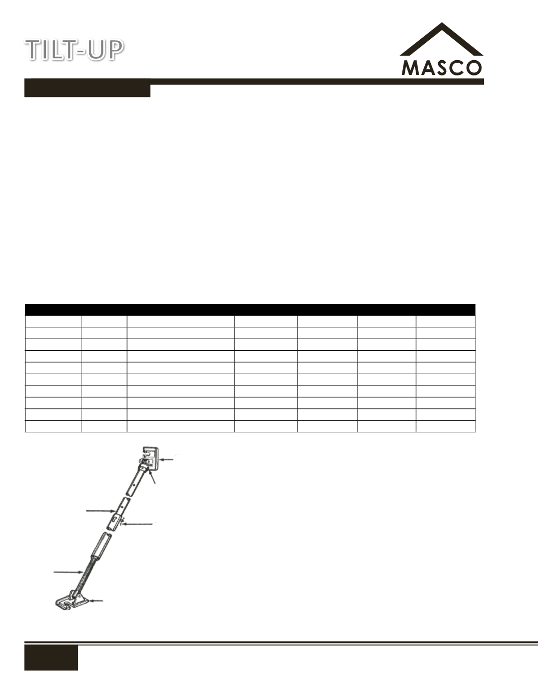
The Tilt-Up Pipe Brace is a time tested accessory which has become the standard in tilt-up construction. Its proper relation of strength
to weight permits ease of handling while providing a rugged brace which is easily adjusted. The tilt-up brace is attached to the
panel before tilting by means of a 3/4" diameter coil bolt threaded into the brace anchor. When the panel is tilted into its final
position, the floor brackets is normally bolted to the floor slab with our T-13 Coil Anchor Drill In Expansion Anchor. Good construction
practices dictate the use of a cut washer under the head of both bolts. A slotted hole on the floor and wall base plate provides easy
attachment and has raised stops to prevent the brace from sliding sideways once the coil bolts have been tightened. Both brackets
remain flat at all times as pivoting action is provided in both the floor and wall brackets. After the panel is tilted to the approximate
vertical position, the Tilt-Up Brace is used to align and hold the panel until it is permanently anchored by further construction. The
floor bracket of pipe brace hardware is attached to a 1-1/2" diameter threaded rod. This galvanized threaded rod has 4-1/2 contour
threads to the inch that are fast and non-clogging. A weld spot at the top of the threaded adjusting rod prevents accidental
removal. Tilt-Up braces are designed for use only in connection with bracing tilt-up precast concrete construction against wind loads.
Due to the problems involved in brick in masonry walls, Mason Supply assumes no responsibility if braces are used to support concrete
block, brick or other masonry walls. The telescoping pipe braces can be rough adjusted in increments of 6" by aligning the pin holes
in the two pipes. Finer adjustment can be attained by simply rotating the entire pipe assembly clockwise or counterclockwise as
required. Ease of rotation is guaranteed by the ball bearing coupler attached to the pipe at the wall bracket.
The B-8 Jumbo Brace is a heavy duty brace that needs no knee bracing or lateral bracing. It is a fixed length brace with
15"-18" of adjustment available for minor field variations. The Jumbo Brace is a full swivel brace that can be rotated about its own
axis after it has been attached for accurate plumbing of panels.
Due to circumstances beyond Masons Supply's control, maximum
brace lengths and styles may vary slightly. It is good construction practice to consider the working length of these pipe braces to be
6" more than their minimum length and 6" less than their maximum length.
No.
Brace
Range
Color Code
Inside Pipe*
Outside Pipe* Wt (lbs)
MAS 100M1 M-1
Approx. 7'-6" to 11'-6"
Red
2" x 6'
2½" x 6'
90.0
MAS 100M2 M-2
Approx. 11'-6" to 19'-6"
Yellow
2" x 10'
2½" x 10'
130.0
MAS 100M6 M-6
Approx. 9'-6" to 15'-6"
Blue
2" x 8'
2½" x 8'
110.0
MAS 100M7 M-7
Approx. 5'-6" to 8'-0"
Black
2" x 4'
2½" x 4'
70.0
DS 10041
B-1
Approx. 7'-6" to 8'-10"
White
1½ **
2" x 3' **
55.0
RC 10003
Lo-Wall
Approx. 7'-9" to 12'-6"
White
2" x 6'
2½" x 6'
90.0
DS 10042
B-2
Approx. 13'-0" to 20'-6"
Yellow
1½" x 10'-6"
2" x 10'-6"
96.0
DS 10043
B-4
Approx. 14'-0" to 23'-6"
Orange
2" x 12'
2½" x 12'
148.0
DS 10044
B-5
Approx. 23'-6" to 39'-0"
Green
2" x 21'
2½" x 21'
226.0
DS 10045
B-6
Approx. 10'-0" to 14'-0"
Blue
1½" x 7'
2" x 7'
75.0
* Measurements are pipe only - screws, swivels not included
1
½
" pipe - 1
⅞
" outside diameter, 1
⅝
" inside diameter
2" pipe - 2
⅜
" outside diameter, 2" inside diameter
2
½
" pipe - 2
⅞
" outside diameter - 2
½
" inside diameter
** B-1 Brace has two inner pipes and a 3' outer pipe with a handle
Note:
All braces must be properly banded
prior to return. (refer to proper
banding illustrations). Braces must
be kept clean or a cleaning charge
will be assessed.
Adjusting
Screw
Foot Plate
Danger!
To prevent accidential removal
of alignment pin, insert a 10d
double headed nail through hole
in alignment pin bending the
protruding portion of the nail to a
45° minimum angle.
Telescoping
Pipes
Ball Bearing
Coupler
Wall
Plate
Adjustable Brace
Adjustable Braces
TILT-UP