



 104 322

104
MASONS SUPPLY COMPANY
Oregon (800) 537-3407 ♦ Washington (800) 537-6216
Clackamas | Eugene | West Eugene | Hillsboro | Medford | Portland | Salem | Wilsonville | Ridgefield | Seattle | Tacoma | Woodinville
M A S C O . N E T
TIEING/HANDSET
Coil-Lag
™
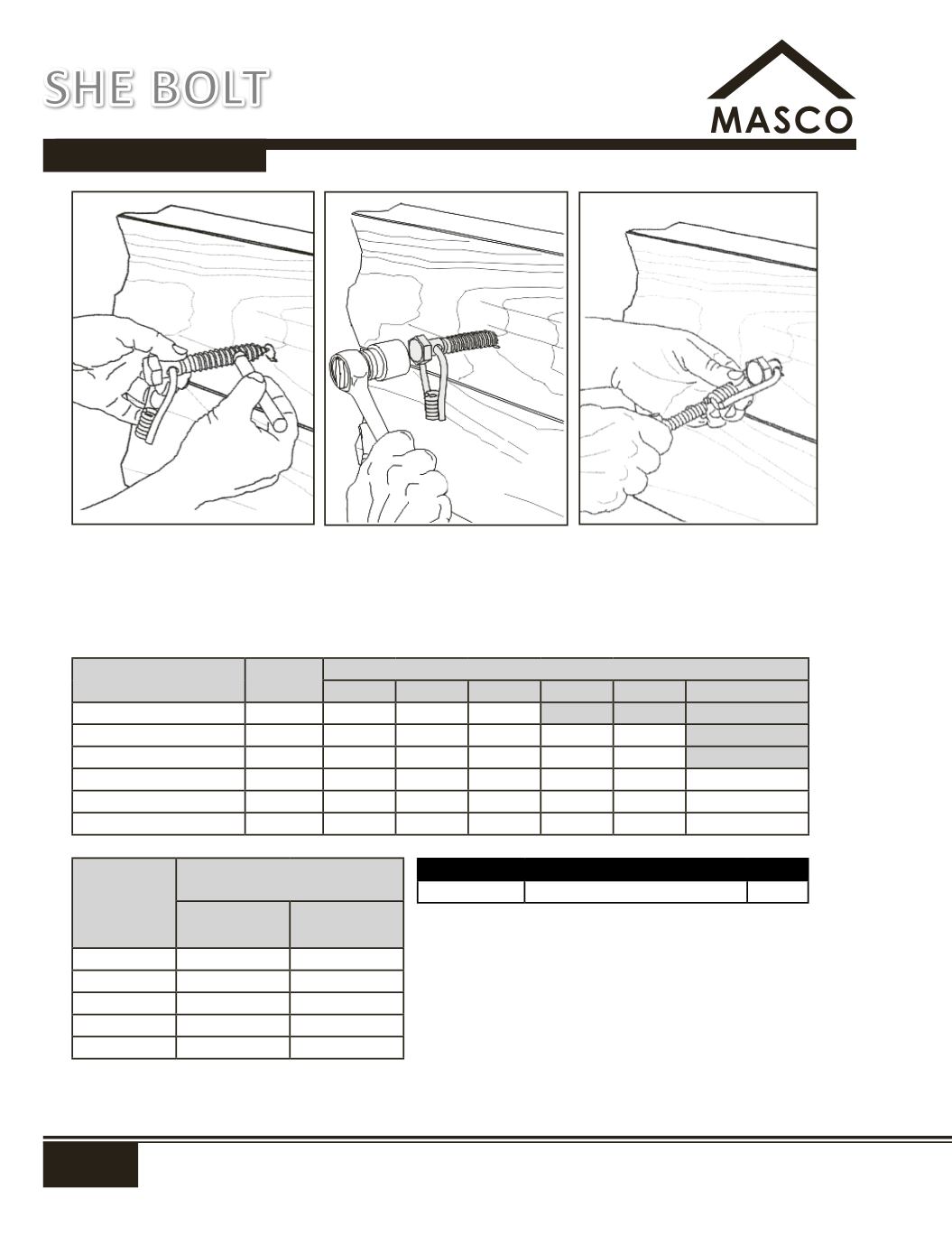
Designed to provide a temporary means of attaching formwork to wood timbers. Typical application: one-sided forming
against soldier piles with wood lagging. Standard hex head lag bolt for sock wrench installation. Swivel loop coil tie end to
accommodate misalignment between lag bolt placement and formwork tie location. Accepts either industry-standard
1/2" coil rod or N/C rod. Bolt is ASTM A307. Swivel loop is AISI C1038. Maximum safe working load is 3,000 lbs. (2-to-1 safety
factor). Actual SWL will depend on pull-out strength of lag in wood and off-axis loading angle.
Wood Species
Specific
Gravity
3
Axial Lag Withdrawal Load in Different Thickness Wood
1, 2
1-1/2"
2"
2-1/2"
3"
3-1/2"
4"
Oak, Red
0.62
1,590
2,120
2,660
3,190
3,720
4,250
Western Larch
0.53
1,260
1,680
2,100
2,520
2,940
3,360
Douglas Fir
0.50
1,150
1,540
1,920
2,310
2,690
3,080
Western Hemlock
0.48
1,090
1,450
1,810
2,170
2,530
2,890
Southern Yellow Pine
0.48
1,090
1,450
1,810
2,170
2,530
2,890
Eastern White Pine
0.37
730
980
1,220
1,470
1,710
1,960
Off-Axis Load
Angle
Off-Axis Load Factor
4, 5
With Grain
Across Grain
10°
1.0
1.0
30°
1.0
0.7
45°
0.9
0.5
60°
0.7
0.4
90°
0.5
0.3
No.
Size
Wt (lbs)
SD SCL4NC 3/4" LAG bolt with 1/2" coil/NC tie.
0.7
1.
Load lbs at approximate 3-to-1 safety factor. Figures based on
p=8,100
3/2
D
3/4
L, where G is specific gravity, D is lag shank diameter, and L is
penetration of threaded portion in wood (from Forest Products Laboratory
Wood Handbook, 1999). Load not to exceed 3000 lbs in any case (chaded
areas represent pull-out values which exceed max. SWL of the Coil-Lag
™
).
2.
All load ratings are for bolt installation into side grain in sound
wood, minimum 1-1/2" from edge and 4" from end of timber.
3.
Specific gravity figures typical for kiln-dried samples of the listed species.
Load ratings based on S.G. figures shown, actual S.G. values for wood vary
widely. Unless acutal S.G. is known, use lower figure for load calculations.
4.
Multiply off-axis load factor times axial lag withdrawal load for
allowable off-axis. Example: 60
o
off-axis, with-the-grain load into 3"
Douglas Fir would be 0.7*2310=1617 lbs max. Remember: this is the
load applied to the swivel loop coil, NOT the axial load on the lag.
5.
Bolt must be threaded into timber until swivel loop is in contact with
wood surface.
SWL provides a factor of safety of approximately 2 to 1.
SHE BOLT